IQ Air Conditioners | on cue for you

ZA - Series R32 Inverter

ZA - Series R32 Inverter   

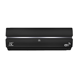
wifi     inverter

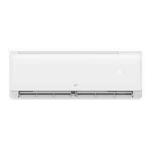
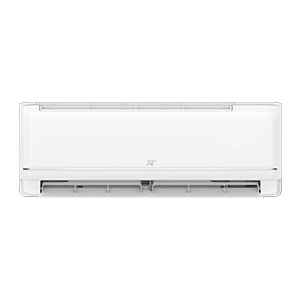
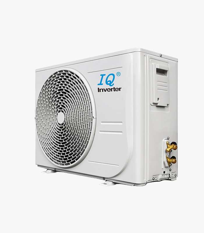
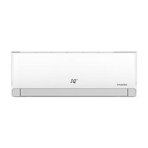
ZA Series R32 Inverter split-unit air conditioner features a sleek, minimalist matt designed to blend seamlessly into modern interiors. As an inverter model, it is engineered for high energy efficiency, providing consistent temperature control while reducing power consumption compared to traditional non-inverter unit

MODEL:
Sizes From: 9K Btu - 24K Btu

  • Description
  • Error Codes

ZA - Series R32 Inverter

Strong Air Supply

Innovative air duct technology overcomes standard air outlet angle limitations. With a broader and extended airflow path, consistent coolness is delivered to every corner of the room.

Ultra Cooling Within 30 Seconds

Featuring advanced fast-frequency boosting, the system utilizes a higher starting capability to achieve rapid cooling and heating in record time.

4D Air Flow

Optimizes air distribution and circulation throughout the room, delivering a much higher level of personal comfort.

Wifi Control

High-efficiency outdoor DC motor ensures better energy efficiency and reliable operation of the unit.

DC inverter

Reliable operation, strong power, high efficiency and energy saving.

ECO Mode

With the Eco function the air-conditioner can ensure the refrigerant in low frequency mode to control lower power consumption. The wall-mounted air conditioner saves 30% of electricity, while the cabinet-type air conditioner saves 20%.

Easier

Convenient assembly and optimized processing ensure simple installation and maintenance, saving you time.
Error Codes

Code Error Explanation & Causes Inspection Procedure & Key Points LED Signal (1 / 2 / 3)
P1 Water full alarm: Tank full, float switch abnormally disconnected, or main control board failure[cite: 3]. 1. Open the water tank plug behind the unit to release water completely. Power cycle the unit[cite: 3].
2. Check if the float switch is stuck or if it registers continuity under normal conditions. Replace if disconnected[cite: 3].
3. If the switch is normal, replace the main control board[cite: 3].
Light / Light / Off [cite: 3]
P2 / PE High voltage switch protection: High-voltage switch opens 3 times within 20 minutes during standby or running[cite: 6]. Frequently caused by low voltage switch cable, switch error, or fluoride leaks[cite: 6]. 1. Verify terminal connection firmness on the main board[cite: 6].
2. Check cable continuity and low-voltage switch state (normally closed, abnormally open)[cite: 6].
3. Inspect system pressure. If disconnected due to a system leak, fix and re-verify[cite: 6]. Replace board if lines/switches are fine[cite: 6].
Off / Light / Light [cite: 6]
P3 / 26 Fluoride deficiency protection: Lack of fluoride, closed stop valve, capillary blockage, coil sensor drift, or compressor failure[cite: 9, 11]. 1. Check refrigeration; if cooling performs normally, inspect if the internal coil sensor fell off or drifted[cite: 11].
2. Confirm stop valve is fully open[cite: 11].
3. Check compressor startup, capacitor values, and winding resistances[cite: 11].
4. Test system pressures (low suggests fluorine lack/blockage; high suggests 4-way valve gas bypass)[cite: 11].
Off / Flash / Off [cite: 9]
P4 Condenser overload protection: Outdoor coil sensor registers a high temp, restricting compressor frequency[cite: 13]. Caused by system blockages, dirty condensers, fan errors, or bad resistors[cite: 13, 16]. 1. Measure outdoor disk sensor resistance (Standard: 20KΩ at 25°C)[cite: 16].
2. Verify system pressure; high levels indicate poor heat transfer or pipe blocks[cite: 16].
3. Confirm whether the fan speed is running too low[cite: 16].
4. Test controller sensor partial voltage loop or replace the external controller[cite: 16].
/ / / [cite: 13]
P5 / F2 Compressor discharge temp protection: Exhaust pipe registers protection states 3 times within 20 minutes[cite: 18]. Caused by sensor drift, lack of fluoride, or system line blockages[cite: 20]. 1. Measure exhaust temperature sensor resistance (Baseline: 50KΩ at 25°C)[cite: 20]. *Note: actual resistance varies based on active temps[cite: 20].
2. Check system pressures for abnormalities[cite: 20].
3. Replace the main control board if sensors and pressures check out[cite: 20].
/ / / [cite: 18]
P6 Heating room high temperature protection: Triggered by internal coil sensor drift or airflow restrictions[cite: 22, 24]. 1. Check and remove any structural blocks around the indoor air inlets[cite: 24].
2. Inspect and thoroughly wash dirty filters[cite: 24].
3. Verify air output volume; check for an ash-fouled internal blower fan and clean it[cite: 24].
4. Measure internal coil sensor resistance drift at room temperature[cite: 24].
/ / / [cite: 22]
P7 Indoor anti-freeze protection: Evaporation temperature drops below 0°C during cooling due to low ambient temps, dirty coils, or low refrigerant[cite: 28]. 1. Feel the connecting pipe or evaporator; if not hot (<60°C), replace the 20KΩ coil sensor[cite: 28].
2. Clean the indoor filter[cite: 28].
3. Check for low fan speed; swap motor or internal board if speed is faulty[cite: 28].
4. Feel evaporator paths to see if one flow line is restricted or incorrectly welded[cite: 28].
5. Recover and weigh in exact factory refrigerant charge[cite: 28].
/ / / [cite: 26]
P8 Outdoor unit overcurrent protection: Operating current values exceed set protection limits[cite: 32]. Caused by transformer errors, control board defects, or lack of fluoride[cite: 32]. 1. Check the current transformer loop to ensure the wire passes through the transformer with the correct number of turns (usually straight through)[cite: 32].
2. Use a clamp meter to measure active unit current draw[cite: 32].
3. Ensure absolute line order mapping matches if replacing control boards[cite: 32].
/ / / [cite: 30, 32]
LO DC overvoltage error: Power voltage supply is running too low, too high, or experiencing volatile spikes[cite: 36]. Affects ODU PCB board[cite: 36]. 1. Test line voltage stability for dramatic dips or high voltage fluxes[cite: 36].
2. Visually inspect the outdoor board for physical fractures or blown components[cite: 36].
3. If the error remains, proceed to the "F1" guidance routine[cite: 36].
Flash / Flash / Light [cite: 36]
L1 / L2 Compressor protections: L1 means phase overcurrent; L2 means lost step protection[cite: 38]. Rooted in broken ODU PCB, line issues, bad supply lines, or compressor failure[cite: 39]. 1. Check the ODU board for trace breaks or component damage[cite: 39].
2. Inspect communication/interconnect wires[cite: 39].
3. Verify compressor terminal lines are mapped correctly, and ensure the compressor is not locked up or running extreme pressures[cite: 39]. Otherwise, refer to "F1"[cite: 39].
Flash / Flash / Light [cite: 39]
L3 Compressor phase error: Caused by incorrectly structured or connected compressor leads[cite: 42]. 1. Double-check compressor wire orientations[cite: 42].
2. For Inverters: Check compressor wiring paths, the outdoor PCB, and pressure switches for structural breaks[cite: 42].
3. For Cooling Only units: Inspect compressor wires, indoor PCB traces, and pressure switches[cite: 42]. If unresolved, refer to "F1"[cite: 42].
Flash / Flash / Light [cite: 42]
L4 Compressor drive module IPM fault: Generally driven by loose or wrong compressor wire installations[cite: 45]. Related to voltage supply, pressure, board, or compressor failure[cite: 45]. 1. Examine the outdoor board structure for circuit breaks[cite: 45].
2. Inspect compressor terminal leads to ensure they are fastened securely and undamaged[cite: 45].
3. Check internal compressor windings for terminal shorts[cite: 45]. If unresolved, reference code path "F1"[cite: 45].
Flash / Flash / Light [cite: 45]
L5 / L6
L7 / LC
Ld
PFC & Motor AD Abnormalities: PFC hardware/software overcurrent (L5/L6), Current detection AD error (L7), PFC current AD fault (LC), or DC fan motor detection AD abnormality (Ld)[cite: 47, 48, 49, 50]. Driven by board failure or heavy incoming line spikes[cite: 50]. 1. Inspect the outdoor main board carefully for trace burns or component fatigue[cite: 50].
2. Test whether input voltage drops too low or climbs too high, and verify overall line stability[cite: 50]. If errors persist after these steps, use manual guide "F1"[cite: 50].
Flash / Flash / Light [cite: 50]
L8 Shunt resistance imbalance fault: Broken ODU PCB, detached or loosely fitted internal terminal connectors, or internal compressor damage[cite: 53]. 1. Check the physical condition of the outdoor board[cite: 53].
2. Trace intermediate wires to confirm lines are not cut and connect tightly[cite: 53].
3. Run electrical diagnostics on the compressor motor[cite: 53]. If code continues to flag, transition to guide "F1"[cite: 53].
Flash / Flash / Light [cite: 53]
L9 IPM temperature sensor error: Faulty outdoor board, abnormal condenser fan speeds, or high pressure thresholds inside the refrigerant lines[cite: 56]. 1. Inspect the outdoor board layout for issues[cite: 56].
2. Monitor the outdoor condenser fan to verify its operating wind speeds are normal[cite: 56].
3. Attach system gauges to verify if pressure is running too high[cite: 56]. If tests pass, execute "F1" actions[cite: 56].
Flash / Flash / Light [cite: 56]
LA Compressor startup failure: Damaged outdoor board, broken/loose intermediate power wires, or internal compressor mechanics locked[cite: 59]. 1. Check the outdoor board for burns or breaks[cite: 59].
2. Ensure terminal plugs on the compressor and module panel are connected firmly[cite: 59].
3. Verify compressor windings[cite: 59]. If the code recurs, use troubleshooting routine "F1"[cite: 59].
Flash / Flash / Light [cite: 59]
LE / LF DC fan motor faults: LE means motor phase error; LF indicates motor lost step protection[cite: 61, 62]. Caused by bad boards, loose plugs, or bad DC motors[cite: 62]. 1. Check the main control panel and modules for physical damage[cite: 62].
2. Verify if outdoor fan speeds drop out of threshold during use[cite: 62].
3. Check system pressure[cite: 62]. If steps are completed and error remains, refer to guide "F1"[cite: 62].
Flash / Flash / Light [cite: 62]
LH DC fan motor IPM protection: Broken board, volatile or out-of-spec voltage parameters, torn wiring, module fault, or a blocked condenser[cite: 65]. 1. Check the outdoor board configuration for broken paths[cite: 65].
2. Inspect wires to ensure everything connects tightly and isn't broken[cite: 65].
3. Verify if the DC fan motor is physically damaged[cite: 65].
4. Clear any debris blocking the condenser coil face[cite: 65]. (If unresolved, follow "F1") [cite: 65].
Flash / Flash / Light [cite: 65]