IQ Air Conditioners | Q Smart R32 Inverter

Q Smart R32 Inverter

Q Smart R32 Inverter  

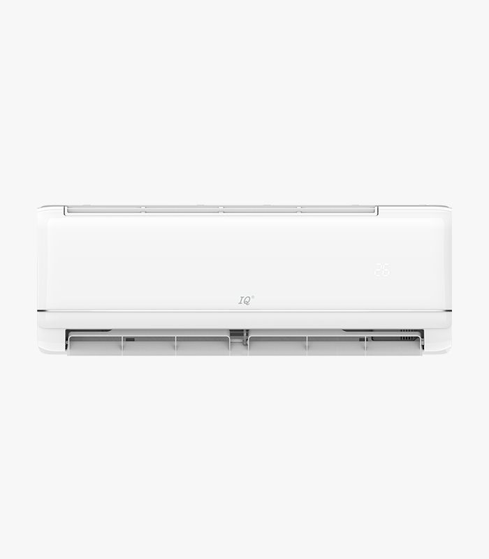
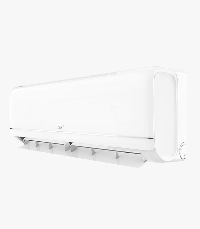
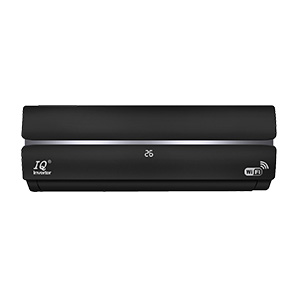
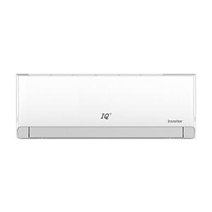
IQ® Q-SMART PLUS Inverter R32 is built to thrive where others fail. Designed for mission-critical applications and the harshest climates, it delivers non-stop performance through a blend of rugged durability, intelligent efficiency, and smart control.

MODEL: 
32K Btu only

  • Description
  • Error Codes

Q - SMART R32 Inverter

Smart Energy Savings: Drops standby power consumption from 4-5W down to just 1W, and features an automated ECO Mode to optimize compressor speed and energy use. 

5th-Gen Automatic Washing: 

A comprehensive 6-step professional cleaning cycle that utilizes 57°C high-temperature sterilization to eliminate 99.9% of bacteria. 

Seamless Wi-Fi 2.0 Control:

Features a built-in Wi-Fi module and a mobile app for convenient remote starts, scheduling, and instant monitoring from anywhere. 

Wide Voltage Protection:

A wide voltage input range (125V–265V) shields the internal PCB from sudden power surges and unstable grid environments.

Extreme Temperature Resilience: 

Features an industry-leading operating range from a frigid -25°C to a scorching 60°C. Whether in a deep freeze or blistering heat, it ensures instant startup and unwavering stability. 

Anti-Corrosion Sheet Metal: 

The outdoor unit is constructed from hot-dip galvanized steel and finished with a high-temperature, pure polyester powder coating applied via advanced Wagner spray equipment for superior weather protection.

Golden Fin Technology: 

Outperforms standard blue fins by offering superior oxidation and corrosion resistance, inhibiting bacterial growth, and enhancing heat exchange efficiency.
Troubleshooting & Diagnostic Codes

Refer to the comprehensive technical guide below to diagnose alerts reported by the internal system or the external panel LED indicators:

Code Error Explanation & Causes Inspection Procedure & Key Points LED Signal (1 / 2 / 3)
P1 Water full alarm: Tank full, float switch abnormally disconnected, or main control board failure[cite: 3]. 1. Open the water tank plug behind the unit to release water completely. Power cycle the unit[cite: 3].
2. Check if the float switch is stuck or if it registers continuity under normal conditions. Replace if disconnected[cite: 3].
3. If the switch is normal, replace the main control board[cite: 3].
Light / Light / Off [cite: 3]
P2 / PE High voltage switch protection: High-voltage switch opens 3 times within 20 minutes during standby or running[cite: 6]. Frequently caused by low voltage switch cable, switch error, or fluoride leaks[cite: 6]. 1. Verify terminal connection firmness on the main board[cite: 6].
2. Check cable continuity and low-voltage switch state (normally closed, abnormally open)[cite: 6].
3. Inspect system pressure. If disconnected due to a system leak, fix and re-verify[cite: 6]. Replace board if lines/switches are fine[cite: 6].
Off / Light / Light [cite: 6]
P3 / 26 Fluoride deficiency protection: Lack of fluoride, closed stop valve, capillary blockage, coil sensor drift, or compressor failure[cite: 9, 11]. 1. Check refrigeration; if cooling performs normally, inspect if the internal coil sensor fell off or drifted[cite: 11].
2. Confirm stop valve is fully open[cite: 11].
3. Check compressor startup, capacitor values, and winding resistances[cite: 11].
4. Test system pressures (low suggests fluorine lack/blockage; high suggests 4-way valve gas bypass)[cite: 11].
Off / Flash / Off [cite: 9]
P4 Condenser overload protection: Outdoor coil sensor registers a high temp, restricting compressor frequency[cite: 13]. Caused by system blockages, dirty condensers, fan errors, or bad resistors[cite: 13, 16]. 1. Measure outdoor disk sensor resistance (Standard: 20KΩ at 25°C)[cite: 16].
2. Verify system pressure; high levels indicate poor heat transfer or pipe blocks[cite: 16].
3. Confirm whether the fan speed is running too low[cite: 16].
4. Test controller sensor partial voltage loop or replace the external controller[cite: 16].
/ / / [cite: 13]
P5 / F2 Compressor discharge temp protection: Exhaust pipe registers protection states 3 times within 20 minutes[cite: 18]. Caused by sensor drift, lack of fluoride, or system line blockages[cite: 20]. 1. Measure exhaust temperature sensor resistance (Baseline: 50KΩ at 25°C)[cite: 20]. *Note: actual resistance varies based on active temps[cite: 20].
2. Check system pressures for abnormalities[cite: 20].
3. Replace the main control board if sensors and pressures check out[cite: 20].
/ / / [cite: 18]
P6 Heating room high temperature protection: Triggered by internal coil sensor drift or airflow restrictions[cite: 22, 24]. 1. Check and remove any structural blocks around the indoor air inlets[cite: 24].
2. Inspect and thoroughly wash dirty filters[cite: 24].
3. Verify air output volume; check for an ash-fouled internal blower fan and clean it[cite: 24].
4. Measure internal coil sensor resistance drift at room temperature[cite: 24].
/ / / [cite: 22]
P7 Indoor anti-freeze protection: Evaporation temperature drops below 0°C during cooling due to low ambient temps, dirty coils, or low refrigerant[cite: 28]. 1. Feel the connecting pipe or evaporator; if not hot (<60°C), replace the 20KΩ coil sensor[cite: 28].
2. Clean the indoor filter[cite: 28].
3. Check for low fan speed; swap motor or internal board if speed is faulty[cite: 28].
4. Feel evaporator paths to see if one flow line is restricted or incorrectly welded[cite: 28].
5. Recover and weigh in exact factory refrigerant charge[cite: 28].
/ / / [cite: 26]
P8 Outdoor unit overcurrent protection: Operating current values exceed set protection limits[cite: 32]. Caused by transformer errors, control board defects, or lack of fluoride[cite: 32]. 1. Check the current transformer loop to ensure the wire passes through the transformer with the correct number of turns (usually straight through)[cite: 32].
2. Use a clamp meter to measure active unit current draw[cite: 32].
3. Ensure absolute line order mapping matches if replacing control boards[cite: 32].
/ / / [cite: 30, 32]
LO DC overvoltage error: Power voltage supply is running too low, too high, or experiencing volatile spikes[cite: 36]. Affects ODU PCB board[cite: 36]. 1. Test line voltage stability for dramatic dips or high voltage fluxes[cite: 36].
2. Visually inspect the outdoor board for physical fractures or blown components[cite: 36].
3. If the error remains, proceed to the "F1" guidance routine[cite: 36].
Flash / Flash / Light [cite: 36]
L1 / L2 Compressor protections: L1 means phase overcurrent; L2 means lost step protection[cite: 38]. Rooted in broken ODU PCB, line issues, bad supply lines, or compressor failure[cite: 39]. 1. Check the ODU board for trace breaks or component damage[cite: 39].
2. Inspect communication/interconnect wires[cite: 39].
3. Verify compressor terminal lines are mapped correctly, and ensure the compressor is not locked up or running extreme pressures[cite: 39]. Otherwise, refer to "F1"[cite: 39].
Flash / Flash / Light [cite: 39]
L3 Compressor phase error: Caused by incorrectly structured or connected compressor leads[cite: 42]. 1. Double-check compressor wire orientations[cite: 42].
2. For Inverters: Check compressor wiring paths, the outdoor PCB, and pressure switches for structural breaks[cite: 42].
3. For Cooling Only units: Inspect compressor wires, indoor PCB traces, and pressure switches[cite: 42]. If unresolved, refer to "F1"[cite: 42].
Flash / Flash / Light [cite: 42]
L4 Compressor drive module IPM fault: Generally driven by loose or wrong compressor wire installations[cite: 45]. Related to voltage supply, pressure, board, or compressor failure[cite: 45]. 1. Examine the outdoor board structure for circuit breaks[cite: 45].
2. Inspect compressor terminal leads to ensure they are fastened securely and undamaged[cite: 45].
3. Check internal compressor windings for terminal shorts[cite: 45]. If unresolved, reference code path "F1"[cite: 45].
Flash / Flash / Light [cite: 45]
L5 / L6
L7 / LC
Ld
PFC & Motor AD Abnormalities: PFC hardware/software overcurrent (L5/L6), Current detection AD error (L7), PFC current AD fault (LC), or DC fan motor detection AD abnormality (Ld)[cite: 47, 48, 49, 50]. Driven by board failure or heavy incoming line spikes[cite: 50]. 1. Inspect the outdoor main board carefully for trace burns or component fatigue[cite: 50].
2. Test whether input voltage drops too low or climbs too high, and verify overall line stability[cite: 50]. If errors persist after these steps, use manual guide "F1"[cite: 50].
Flash / Flash / Light [cite: 50]
L8 Shunt resistance imbalance fault: Broken ODU PCB, detached or loosely fitted internal terminal connectors, or internal compressor damage[cite: 53]. 1. Check the physical condition of the outdoor board[cite: 53].
2. Trace intermediate wires to confirm lines are not cut and connect tightly[cite: 53].
3. Run electrical diagnostics on the compressor motor[cite: 53]. If code continues to flag, transition to guide "F1"[cite: 53].
Flash / Flash / Light [cite: 53]
L9 IPM temperature sensor error: Faulty outdoor board, abnormal condenser fan speeds, or high pressure thresholds inside the refrigerant lines[cite: 56]. 1. Inspect the outdoor board layout for issues[cite: 56].
2. Monitor the outdoor condenser fan to verify its operating wind speeds are normal[cite: 56].
3. Attach system gauges to verify if pressure is running too high[cite: 56]. If tests pass, execute "F1" actions[cite: 56].
Flash / Flash / Light [cite: 56]
LA Compressor startup failure: Damaged outdoor board, broken/loose intermediate power wires, or internal compressor mechanics locked[cite: 59]. 1. Check the outdoor board for burns or breaks[cite: 59].
2. Ensure terminal plugs on the compressor and module panel are connected firmly[cite: 59].
3. Verify compressor windings[cite: 59]. If the code recurs, use troubleshooting routine "F1"[cite: 59].
Flash / Flash / Light [cite: 59]
LE / LF DC fan motor faults: LE means motor phase error; LF indicates motor lost step protection[cite: 61, 62]. Caused by bad boards, loose plugs, or bad DC motors[cite: 62]. 1. Check the main control panel and modules for physical damage[cite: 62].
2. Verify if outdoor fan speeds drop out of threshold during use[cite: 62].
3. Check system pressure[cite: 62]. If steps are completed and error remains, refer to guide "F1"[cite: 62].
Flash / Flash / Light [cite: 62]
LH DC fan motor IPM protection: Broken board, volatile or out-of-spec voltage parameters, torn wiring, module fault, or a blocked condenser[cite: 65]. 1. Check the outdoor board configuration for broken paths[cite: 65].
2. Inspect wires to ensure everything connects tightly and isn't broken[cite: 65].
3. Verify if the DC fan motor is physically damaged[cite: 65].
4. Clear any debris blocking the condenser coil face[cite: 65]. (If unresolved, follow "F1") [cite: 65].
Flash / Flash / Light [cite: 65]